The Revit standard circuit tag we are using is formatted Panel Name / Circuit, with Circuit being (Phase/Way). The industry standard for circuit tagging in the UK is however Panel Name / Way / Phase. From what I can tell there is no way of customising this directly into Revit. After a bit of research online I've found that this problem came up quite a few times on forums, with no particular fix however.
To work around it I assigned two shared parameters to the Wires category in Project Parameters. These two parameters would then allow me to modify the circuit tag with the format I needed.
 |
| Revit Wire Properties |
However this workaround would require someone to manually populate the newly created Phase and Way parameters. One quicker way of doing this would be to export the circuit parameters into an excel file and manipulate the data there. Even though this would be slightly faster, it would still be quite a time consuming workflow by introducing excel into the scheme. Whenever possible I try to avoid data manipulation in excel if it can be avoided.
The task seemed perfect for Dynamo and a good opportunity for me to put my limited Python knowledge to use.
 |
| Dynamo Diagram |
 |
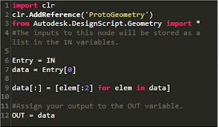
| Python - Circuit Phase data extraction |
 |
| Python - Circuit Way data extraction |
The Dynamo diagram would read all the Wire Circuits Parameter values in the model and then using the Python script it would break the data into two. In my case I had L2/1, L2 being the phase and 1 being the Way. The new data would then be pushed back to Revit and the newly created parameters (Phase and Way) would be populated based on the Circuit data.
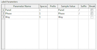
Last step of the exercise was to modify the Revit Wire Tag Family to work with the newly created parameters.
 |
| Revit Wire Tag Family - Edit Label window |
